
Powering the model.
For those who are interested in the electronical side of things, this page will explain the different techniques I have used to electrify, light and manage the power to this model railway. Because I need this layout to be as portable as possible, right from the begining I had to think ahead as to how I could make things such as the delicate "Viessmann e-motion models" removable, but still have power going to them. Read on to find out how....
The Buildings
In order to illumnate the various buildings such as the station house, ticket office, gentlemens washroom, water tower and signal box, I needed to have a lighting system that could either be removed when not in use or one that could be in permanent place but not interfere with the portability of the buildings.
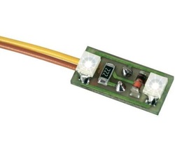
Before I eventually settled on the lighting system I now have in place, I thought of several different ways of lighting the layout. On previous layouts I have created contact circuits, where the lighting works when the models are placed on a copper plate completing the circuit. This worked well, however it is very time consuming to do, and the circuit can be broken if the model is slightly out of allignment. Another option was to use the Hornby Scaledale lighting system. A system using mini lights and mini plugs, but this means each time you wish to move the buildings, they would need to be unplugged. Finally after some research I found a company called "Viessmann" from Germany who have a line of LED lights with circuit chips that can be permantely wired and glued in place. They work as uplighters, so instead of attaching the lights to the buildings, you can place them on the floor underneath the building and they will light from below. In order to help light up the buildings I built little platforms to place the LEDs on, this created less shadows and meant I could light up stairs in buildings rather than just the ground floor. (see below)
Controlling the lights (and things)
As a child I had a facination with models operated by push buttons, I enjoyed the way the viewer could also be involved in the operation of the model and not just be on the side lines. So I made a concious decision that my model would have push buttons to allow the audience to interact with it.
All the lights are wired up (some in pairs) so that you can turn different sections of the lighting on independently giving a natural feel to it and there are also several other little electronically powered features on the model that are also button controlled.
eMotion Figures
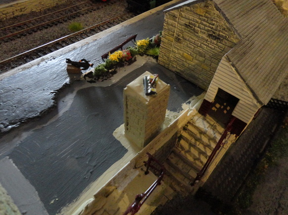
One of the other nice little features that I have installed on the model come from a fascinating little line of figures also created by Viessmann of Germany called eMotion figures. They are HO scale figures (which is an acceptable scale for OO as they are not that different) in various poses, that due to the fact they have a micro chip installed and a small rod, can actually move quite realistically.
Currently I have two installed on my model (one on each 4 ft x 2 ft lengths) a painter who is painstakingly painting a refuse bin and a bricklayer who is finishing of a wall next to a hut. My plan in to eventually have some more of these pleasant models on the layout as they add a nice touch of movement, and catch the eye in a whimsical sort of way.
All the lights are wired up (some in pairs) so that you can turn different sections of the lighting on independently giving a natural feel to it and there are also several other little electronically powered features on the model that are also button controlled.
eMotion Figures
One of the other nice little features that I have installed on the model come from a fascinating little line of figures also created by Viessmann of Germany called eMotion figures. They are HO scale figures (which is an acceptable scale for OO as they are not that different) in various poses, that due to the fact they have a micro chip installed and a small rod, can actually move quite realistically.
Currently I have two installed on my model (one on each 4 ft x 2 ft lengths) a painter who is painstakingly painting a refuse bin and a bricklayer who is finishing of a wall next to a hut. My plan in to eventually have some more of these pleasant models on the layout as they add a nice touch of movement, and catch the eye in a whimsical sort of way.

This little chap works very hard for his wages, check out the video accross the page.
|
|
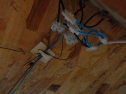
With the eMotion figures as they have very fragile components I wanted to make them removable too just like the majority of the buildings, so I had a long hard think as to how this could be achieved. The problem that I have is that I need the figure to be wired in for power, but I also need to be able to take it off the model as and when needed. The figures motor housing is directly underneath the model stand plate, is about 3 inches long and needs to be hidden under the base board with a power supply.
My first option would have been to wire and un-wire the little fella everytime I move him, this could be done using the cheap terminal connection blocks available in most DIY stores. But apart from the time it takes, through years of walking way too fast my knees are not as good as they used to be and I really need avoid kneeling down underneath the board as much as possible. So I suddenly came up with the idea of installing some simple speaker terminal connections, the ones that are spring loaded to allow for quick release, this way I can move them quite quickly if needed.
To aid with guiding the wires through the 12mm hole in the layout and through to the underside where the speaker terminal connectors are I used kebab skewers attached to the base of the motor housing, so that it just protrudes from underneath the layout board.
This has worked very well and so I have used the same proceedure attaching street lamps to the layout too. Currently I have installed 4 lamps, but eventually the station platform will have 7 working lamps. Not everything always goes to plan though, during my latest installation of a new lamp I accidentally contaminated the central tubing that hosts the bulb and wire with epoxy resin.
This caused the very thin wires to snap, and completely write off the lamp, so I will use it for spare parts and have to order a new one.
That was an expensive mistake to make, so I won't be doing that again in a hurry!
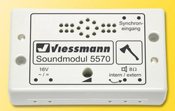
New - For Christmas 2012 I was very lucky to receive as a present a sound module for my little woodcutter man. This is a very cleaver bit of kit allowing syncronised sound to be emmitted from a speaker hidden under the layout. I also recieved enough vouchers and money to order another Viessmann model along with another sound module to go with it. So the next paragraphs are dedicated to the installation of these two new additions..